Dear Shop Doc,
We have a CNC Swiss that we use to turn very small precise parts. When a part has several different diameters I notice that when one diameter is on the nominal dimension, often the others are off nominal by several tenths. Is this due to different tool pressure at the different depth of cuts? Is there a solution?
Tiny Turner
Dear Tiny,
I doubt the issue is from tool pressure. It is more likely that your turning tool center height is off. Old timers will tell you that tool center height is very important in very small turning. I’ll attempt to explain why that is so.
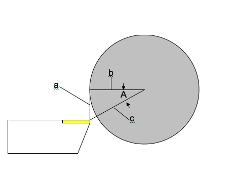
In the following example take a look at how being off center can affect the diameter being turned. First let’s assume that if your tool was brought to X0, the tip would be dead on the centerline of the bar.
Line “a” is how far your tool is off center. Line “b” is your programmed X-axis dimension. Line “c” is the actual distance to the cutting edge of the tool or ½ the actual turned diameter dimension on your work.
Imagine making Line “b” longer and longer (turning progressively larger diameters) and you’ll see that Angle “A” flattens out, which in turn will make Line “c” shorter relative to Line “b.” In other words the error becomes less the larger the diameter you turn is. So when turning very small diameters it is critical to be on center.
The Pythagorean Theorem tells us that a ²+b ²=c ². Using that information, let’s assume that your tool is 0.003” off center, and you are turning a 0.030” diameter (side a=0.003”, side “b”=0.015”). Side c therefore is equal to 0.0153” because c=√ (.003 ²+.015 ²), so your turned diameter will be 0.0306” or will be 0.0006” off of nominal size.
Now assume you are using the same tool to turn a 0.125” diameter. Running the same math we find that the turned diameter (rounded) will be 0.1251” or will be 0.0001” off of nominal size.
Since the 0.030” diameter was 0.0006” off of nominal we have a differential of 0.0005” between the two dimensions. It follows that when you offset one dimension to nominal size, the other dimension will be 0.0005” off of nominal. All of which makes it difficult to dial in the workpiece without editing the program (bad), or using two separate offsets (nearly as bad).
You can also add a macro variable to the programmed dimension. But when you think about it, all that does is provide a convenient way for the operator to edit the programmed dimension. It’s better to fix the root cause of the problem by getting the tool on center.
You can use this information to calculate how far your tool is off center and correct it with an offset assuming you have Y-axis capability. Small capacity Tsugami Swiss lathes have a feature built into the control to calculate tool height using this principle. But you can see it works best at very small diameters where Angle A and the resulting error is greater.
There can also be mechanical reasons for disparity between turned diameters. If your tool is on center check for backlash, flex in the machine/tool holder, and of course the fit of the material to the guide bushing.
Question: When you watch the Super Bowl, are you more interested in the game or the commercials?


2 Comments
This same effect is also noticed when milling, interpolating a circle using polar coordinate mode, and a live axial tool. In this case you will end up with an oval.
Centerline is also important when using carbide tooling. If the tool is below center it is cutting material that has rotational forces pulling away from the surface of the carbide. As carbide is strong in compression it is weak in tension and the below center condition tends to pull away micro chips on the cutting edge surface reducing tool life. On center to a couple of thou. above center will keep the carbide in compression that can improve tool life. Most pressed carbide inserts have a height tolerence of -/+.005 so centerline may very from lot to lot of inserts. – another thing to keep an eye on.
Roger