Today’s Machining World Archive: March 2010, Vol. 6, Issue 02


The customer sends you a print. It specifies material, dimensions and surface finish. It’s up to you to make the part to spec, and you’re hoping to put in as little machine time as possible. You know how long it would usually take to make the part, but you have control of many aspects of the process, and maybe there is something you can do to speed it up. You select the tool and set the feeds and speeds, and your CAM system provides the tool path. You can select the mechanical capacity of the machine, within the limits of the machines you have in the shop.
Where there is a lot of material to remove, as with dies, molds, aerospace parts and a variety of other jobs, a big part of how you stay competitive is in being able to remove as many cubic inches of metal as possible per minute while maintaining good surface quality and acceptable tool life. There are many different approaches to maximizing those cubic inches/minute. A good place to start investigating your options is with your tooling supplier. Most have had a lot of experience with applications like yours. They can offer a range of cutting tools to do the job and provide help in applying them, no matter which way you decide to maximize your material removal rate.
Large Depth of Cut
The first approach you might think of is to take a larger depth of cut than you might normally—as large of a depth of cut as possible. You’ll need lots of torque and horsepower, strong tools designed for this type of service and superior workholding. If you’re set up for this kind of heavy material removal, it can save you a lot of machining time on the parts that need it.
Many shops are accustomed to thinking in terms of going light and fast, said Kenneth Accavallo, product specialist for milling products, Sandvik Coromant US, Fair Lawn, N.J. “It’s hard to explain when a company is not used to doing heavy milling. They have to look at the machine’s horsepower, rigidity, torque, the size of the spindle” to get those cubic inches of material removal.
Accavallo said he has been seeing more interest in this approach recently. “A lot of manufacturers of machine tools seem to be going bigger now—bigger machines, bigger spindles. Customers buying them want to explore the capabilities of [their new] machines.”
Tooling is critical for these challenging applications. Accavallo explained two new face mill lines from Sandvik designed for heavy material removal. The CoroMill 300 features round inserts, he said. The round shape gives the inserts extra strength. The CoroMill 360, available in sizes up to 20 inches in diameter, is designed to take up to a 0.709” depth of cut. One application in the nuclear
industry, Accavallo said, is heavy roughing on Inconel billets. “Customers want to take off as much material as they can.”
High-feed

If you reduce the depth of cut from the usual, you can run more surface feet/minute (SFM) and feed faster, said Todd Miller, milling product manager, Seco Tools, Troy, Mich. The net result can be material removal rates up to one-third faster than the conventional approach, with the added benefit of increased tool life.
Miller gave the example of machining steel, 4140. With a conventional 4” face mill with seven teeth, as listed in the tooling catalog, you’d take a 0.120” depth of cut, with 650 SFM, and a feed of 0.012” per tooth. This would give you feed rate of 52” per minute, and you’d remove 25 cubic inches of material per minute. With a high-feed 4” mill, you’d take a 0.060” depth of cut, 0.040” feed per tooth, 985 SFM. That would give you a 245” per minute feed rate, and 63.6 cubic inches/minute of material removal. This represents a 27 percent increase in material removal rate.
The extremely fast feed—in this example, 245” per minute versus 52” per minute for conventional machining—can be alarming when you first run it, Miller says. And older machines may not be able to handle that rate of feed. The mechanical stability of the ways and feed mechanism, as well as the machine control, need to be able to handle it.
Tool Path
Another way to increase material removal rate is to use your CAM system to provide a tool path that allows the highest material removal without undue strain on the tool. An innovative way to do this is to optimize the angle at which the tool engages the workpiece. This can minimize the forces on the tool, allowing you to run it to remove material as fast as it is capable.
Mike MacArthur, applications engineer at RobbJack Corporation, Lincoln, Cal., gave an example of a titanium part that had previously taken about four hours to cut. With the controlled-engagement-angle approach and the proper tooling, the cut was complete in 15.7 minutes.
He gave other examples. “We cut stainless steel at 150” per minute and titanium at 75” per minute, instead of 2” per minute,” MacArthur said.
The different CAM software packages have their own names for this capability. MacArthur has found that customers often already have the capability in-house in their existing CAM system, but don’t know how it works. He recommends they call their CAM software provider and ask, “Does this software have the ability to control the tool engagement angle?”
Tool manufacturers are designing tools that take advantage of these newer programming approaches. For example, RobbJack has a 3-flute end mill designed for use in aluminum, which incorporates vibration dampening. In another line of tools designed for high removal rates, the flutes are designed with different helix geometries to prevent vibration. This can allow up to double the material removal rate, he said. Where a conventional tool would squeal and vibrate and damage the cutting edges, this line of tools stays very stable and quiet while it cuts, MacArthur said.
Other tool-path methods are available that can improve material removal rates are:
- Plunge milling
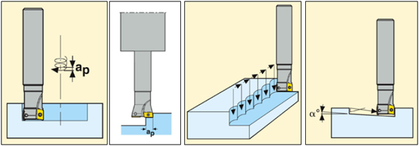
As the name suggests, a specialized plunge mill cuts into the material in the Z direction, then withdraws and plunges again about half a diameter away. Plunge milling can be done from an edge or the outside of a hole, or the tool can gradually ramp its way into the workpiece. Repeated plunges can remove a lot of material. Because the cut is in the Z direction, the cutting
forces are transmitted straight into the spindle, which minimizes side loads and vibration.
- Helical interpolation
The tool starts on the surface and ramps its way into the material in a circular pattern, making a hole or pocket.
- Trochoidal milling
This uses a similar tool that cuts into the workpiece from the side, making a slot. The tool is generally about half the width of the slot and advances along a straight line, making small circles in a swirling kind of motion, gradually advancing the slot through the material.

Chip Evacuation
Tool manufacturers recommend dry machining for many heavy material removal processes, especially in steel, Miller said. Since you’re not applying a flow of cutting fluid, chip evacuation can become a challenge when cutting dry. On horizontal machines, this doesn’t pose a problem, of course—the chips fall out of the cut by gravity. On vertical machines, however, chip accumulation can be a problem, especially when you’re working in cavities or pockets. In this case, Miller suggests using an air blast to blow the chips out of the way. As a last resort, you could use a stream of cutting fluid, but that tends to reduce your tool life considerably, Miller said, as the cooling effect on the tool can produce thermal cracks in the tool’s coating.
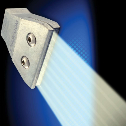
Specially designed high-power air nozzles can remove chips effectively from the cutting area with a maximum of pressure and a minimum of noise. Exair Corporation, Cincinnati, Ohio, manufactures a line of high efficiency air nozzles that provide a high-force, focused-flow, low-noise air blast suitable for chip evacuation, while using a relatively small amount of compressed air. Which nozzle to use? If you can use a normal compressed air gun to blow chips off the part, Exair’s 1100 family of Super Air Nozzles will do the job, Exair marketing manager Gary Gunkel said. If a higher-force air blast is necessary, Exair’s 2” Super Air Nozzle provides higher force, also in a controlled pattern and at high efficiency.
No matter which approach to high material removal you decide to use, you will be able to turn more metal into chips faster using these methods. The job, the material and your machining and programming capabilities will determine which approach you can take. In the past, high material removal rate machining had the reputation of being a “black art,” MacArthur said. But you should talk to your tooling vendor. With the proper tooling and the right programming, machining at a high material removal rate is very predictable, he said.
